The usage of microwave (MW) plasma sources comes along with many upsides compared to devices using radiofrequency (RF) waves for igniting and maintaining low pressure plasmas.
In the following we would first like to give insight into the broad variety of microwave plasma applications.
Then we present a thorough investigation of the obtained physical plasma parameters for a range of different gas recipes, gas pressures, flow rates, and power inputs.
We present plasma gas temperatures, electron densities and relative radical densities based on optical emission spectroscopy (OES) measurements.
Furthermore, we investigated the plasma ignition times for different parameter sets, temporal stability of the plasma temperature as well as the reflected microwave power, showcasing the efficiency of the processes.
Index Terms- microwave plasma generation, remote plasma source, downstream plasma source, low pressure plasma, plasma gas temperature, electron density, etch rates, reflected power, ignition time
The Remote Plasma Source (RPS) model Industry 4.0 is a complete microwave system designed for easy turnkey integration. It offers a wide process range of gases, gas flow rates, pressures and power.
The product is optimized for a long lifetime and low cost of ownership.
Technical dates of the product are presented in Table 1. The applicator is optimized so that plasma ignition is possible with all process gases mentioned in the table without the need for argon as an ignition gas.
Microwaves (2.45 GHz) are generated using a magnetron. Through a waveguide and an antenna, they enter a resonance cavity where a very high electric field strength is realized. Free electrons in the process gas are accelerated and perform inelastic collision processes with heavier particles, leading to a chain reaction that results in the ignited plasma.
The ignition is happening in a ceramic cup that allows the usage of fluorine and non-fluorine chemistries.
Figure 2 presents how the antenna transports the microwaves into the plasma applicator. The geometry is optimized for the frequency of 2.45 GHz so that a resonance is realized, and a high electric field strength is achieved inside the ceramic tube to ensure a fast and consistent plasma ignition.
If the plasma has not yet been ignited, or if there is no gas flow, a high fraction of the microwave power would be reflected back towards the magnetron head. Therefore, an isolator is integrated which absorbs any microwave power that couldn’t be absorbed by the plasma.
As the microwaves are entering the plasma gas, the much lighter electrons can follow the high frequency field change in contrast to the heavy ions. Before the field polarity changes with a frequency of 2.45 GHz, the electrons perform inelastic collisions with heavier particles, which results in an energy transfer and different processes such as dissociation, ionization and excitation. Since the heavier ions can barely build up speed until the field direction changes again, the energy is mostly absorbed by the electrons in the plasma gas, which results in low energy ions. The situation is depicted in Figure 3.
The fact that heavy ions in a microwave plasma have low kinetic energy is one of the main differences in comparison to radiofrequency plasma sources. For MW plasmas, the effect of ion bombardment on the sample is negligible, which results in pure-chemical etching processes.
An electromagnetic wave can only propagate in a plasma if the EM-wave frequency is larger than the plasma frequency, otherwise it gets exponentially damped.
Since the frequency of a MW is much larger than that of a RF-wave, the waves can penetrate at a higher plasma frequency.
Because of that, usually for MW generated plasmas a higher electron density can be realized as compared to RF technology.
Microwave plasma technology enables a variety of different applications:
1. Decapsulation of chips/microchips
2. Chemical vapor deposition
3. Surface passivation and activation
4. Cleaning of plasma deposition chambers
5. Waste gas cleaning
6. Fast photoresist and polymer removal
Alongside the following upsides:
1. Pure isotropic etching
2. Highly selective etch processes
3. No ion bombardment/pure chemical etching
4. Low thermal load on the substrate
5. No electric field and plasma in the process chamber
6. No additional ignition gas is necessary
7. No charging of the substrate
To characterize the RPS, ignition time measurements have been performed using a variety of different gas mixtures, flow rates and two different pressures. The results are shown in figure 4. From the figure most of the investigated recipes are igniting very quickly, while only some gas mixtures of nitrogen and carbon tetrafluoride are igniting slower than 200 ms.
Usually, because of its high density, the plasma can’t absorb 100% of the forward microwave power. This leads to a small amount of power being reflected back towards the magnetron head. The integrated isolator absorbs 100% of the reflected power and prevents the magnetron and other components from taking any damage. Using a diode, the reflected power can be measured as of a voltage signal. Opposite to RF plasma sources, reflected power is not harmful to the system and can instead be used as a measure for process efficiency and process control.
For a variety of different plasma gas recipes using oxygen, nitrogen and carbon tetrafluoride as well as different pressures (1-6 Torr), different flow rates (500-5000 sccm) and a broad range of powers (400-3000 W) the reflected power has been investigated. For the broad range of measurements, the percentage of power being reflected reaches values of <5% in the power range of 2 kW-3 kW in all cases.
The following results are based on optical emission spectroscopy measurements. The experimental geometry is shown in Figure 5. For the measurements, a spectrometer from PLASUS (EMICON SA) was used. The emitting light from the plasma was measured in between the RPS and the process chamber using a T-shaped vacuum pipe. This geometry was chosen so that the plasma properties can be investigated as the plasma stream is entering the process chamber.
Measurements have been performed using a plasma recipe with 20% nitrogen and 80% oxygen. A small amount of nitrogen added to an oxygen plasma is known to increase the oxygen radical density.
Plasma properties have been studied for different flow rates and powers.
Figure 6 shows the plasma gas temperatures that have been obtained for all measurement runs. The temperatures have been evaluated using the free software “massive OES” [2] which allows batch processing of spectra. For the evaluation, the C-B band system of molecular nitrogen in the range of 300-380nm was used.
As can be seen in the figure, the plasma gas temperature increases almost linearly which power, and it decreases with an increasing flow rate.
Figure 7 shows the electron densities in the plasma for the data plasma recipe, flow rate and power range. These data points have been obtained by evaluating the line intensity of two nitrogen spectral lines and using an approximated formula for the electron density [3].
The electron density shows almost the same dependency on power and flow rate as the plasma gas temperature, an increase for higher power and a decrease for higher flow rates.
The spectra of a typical plasma recipe used for photoresist etching containing oxygen, nitrogen and CF4 is shown in Figure 8 for three different power levels.
The spectra are dominated by the oxygen radical peaks, while fluorine radical peaks and a contribution of nitrogen molecules are also visible.
By using a small amount of Argon as an actinometer, it is possible to evaluate relative radical densities of oxygen and fluorine radicals in the plasma by comparing specific peak intensities in the emission spectrum of the plasma (Ar 750 nm, O 844 nm, F 704 nm). Calculating absolute values would require knowledge of the shape of the electron energy density function (EEDF), which wasn’t obtained in the present work.
The calculated values are shown in Figure 9. The graph shows that the oxygen radical density is increasing more strongly with power than the fluorine density.
The densities seem to increase in a linear fashion, while the slope shows a kink at about 2000 W.
Operating microwave plasmas in pulsed mode can have several advantages such as higher etching rates, better uniformity and less damage to the sample.
The power supply (article number: MX3000D-171KL) allows a pulsed mode of active time and down time down to 250 microseconds, allowing a pulsing frequency up to 2 kHz at 50% duty.
Figure 10 shows the spectrum of an O2, N2, CF4 plasma. The peak at 844 nm is related to the oxygen radicals in the plasma and is showing an increase and a maximum for a pulsing frequency of 100 Hz. The same is true for the peak relating to the fluorine radicals in the plasma.
To investigate the temporal stability of the plasma gas temperatures have been evaluated for several time stamps after ignition had taken place. The measurements were performed in a nitrogen-oxygen plasma.
The results are shown in Figure 11 for three different power levels. The data shows that the plasma temperature reaches a constant level almost immediately after ignition with no visible “warm-up” time.
References
[1] Spectroscopic Analysis of CF4/O2 Plasma Mixed with N2 for Si3N4 Dry Etching, W. S. Song, J. E. Kang, S. J. Hong, Coatings, 2022
[2] J. Vor¨ıˇc, P. Synek, L. Potoˇc¨ıkov¨ı, J. Hnilica, and V. Kudrle, “Batch processing of overlapping molecular spectra as a tool for spatio-temporal diagnostics of power modulated microwave plasma jet,” Plasma Sources Science and Technology, vol. 26, no. 2, 2017
[3] Fatima, H., Ullah, M.U., Ahmad, S. et al. Spectroscopic evaluation of vibrational temperature and electron density in reduced pressure radio frequency nitrogen plasma. SN Appl. Sci. 3, 646 (2021). https://doi.org/10.1007/s42452-021-04651-z
To comply with future legislation aimed at reducing pollution and given the different designs, ages and capacities of existing plants and processes, the industry needs to have a wide range of technologies from which to choose. The application of process intensification principles using alternative heat sources could contribute to the development of sustainable industrial processes, especially given the growing urgency to move away from fossil fuels and the potential role of clean energy in this transition. The conversion of industrial processes to all-electric power is widely accepted as a solution for the industry due to its potential to significantly reduce the CO2 emissions in a future fossil-free energy supply(1). However, the immense diversity of the industrial sector means that there is no one-size-fits-all solution to achieving net-zero emission targets. Moreover, with heat transfer to different processes being one of the clearly identified bottlenecks in industrial processing, this transition is difficult for many industries that require high temperature processing, high thermal energy rates and short payback periods for investments.
These challenges open up new opportunities for industry's transition to a resilient, energy-efficient, renewable and climate-neutral economy, ranging from implementing commercially available solutions to experimenting with new technologies(2).
Plasmas can be applied to chemical processes at high and low gas pressures, offering several advantages such as a simple one-step process that can be started and stopped instantly, and they provide high energy density for very fast reactions.
New concepts of modular plants and decentralised production facilities are rapidly gaining acceptance in the industry and are relevant to microwave plasma-based technology as it gives new directions to Power-to-X technologies, opening up a new range of mechanical, chemical and metallurgical processing techniques.
Microwave plasma offers several advantages over other plasma technologies, including higher ionisation efficiency, reduced risk of contamination and damage to sensitive components as microwave discharge does not involve electrodes, and a dense non-equilibrium plasma with electron density ɳe = 1013 cm− 3 is generated over a large pressure range. As a result, microwave plasma technology can simultaneously achieve high electron density and high electric field strength, resulting in higher electron temperatures. In addition, the use of microwaves as an all-electric technology is economically attractive because microwave generators are commercially available at 2.45 GHz up to 15 kW and 915 MHz up to 100 kW. Their energy efficiency is high(3), allowing both low electrical energy costs and high productivity to be achieved.
Power-to-X (P2X) and Power-to-Gas (P2G) are generic terms used for technologies that convert grid and/or renewable electricity into carbon-neutral synthetic fuels such as hydrogen, synthetic natural gas, liquid fuel or chemicals. These can be used in sectors that are difficult to decarbonise or, unlike electricity, can be stored for later use.
2.1 Decarbonising / Conversion of CO2
Microwave plasma dissociation and conversion of carbon dioxide (CO2), the main greenhouse gas, has been considered in the context of Carbon Capture and Utilization (CCU) approaches. CCU is the sequestration of CO2 and its conversion into energy carriers or value-added chemicals. Many different routes are being developed and investigated including CO2 fixation, e.g., inorganic carbonates, growing algae for biofuel/biodiesel production, dry reforming of methane (CH4) – eq. 1, the direct conversion of CO2 into carbon monoxide (CO) and oxygen (O2) – eq. 2.
(1) CO2 + CH4 ↔ 2CO + 2H2
(2) CO2 ↔ CO + ½ O2
The resulting CO can then be further processed through the water-gas shift reaction, eq. 3, to hydrogen (H2), important feedstocks for the synthesis of ammonia (NH3), liquid fuels such as synthetic diesel, methanol, etc.
(3) CO + H2O ↔ CO2 + H2
2.2 Hydrogen for fuel and chemical synthesis
Molecular H2 is considered to be the most important fuel for the energy transition. Today, more than 96 % of H2 is produced from fossil resources such as coal, natural gas, and oil. To reduce the environmental impact, new alternative solutions are being developed, such as water electrolysis using electricity from renewable resources, such as wind energy, solar energy, geothermal energy, biomass etc.(4) An alternative technology for the production of H2 is the direct microwave plasma conversion of CH4 contained in biogas or in natural gas, since both feedstocks contain mainly CH4, i.e. up to 60-70 vol% for biogas and >80 vol% for natural gas. In this process there are no CO2 emissions, the electricity/energy input is much lower than for water electrolysis and the co-products, i.e. carbon black (C) obtained mainly in the plasmalysis process at atmospheric pressure – eq. 4 and the C2 fraction - acetylene (C2H2) and ethylene (C2H4) - obtained at moderate pressures – eq. 5, are products with great industrial value.
(4) CH4 ➟~atmospheric pressure➟C + 2H2
(5) 2CH4 ➟ 50 - 150 mbar ➟ C2 H2 + 3H2
In these reactions, the H2 produced is classified as either green H2 or turquoise H2, depending on the feedstock, biogas or natural gas, respectively.
The microwave power generated by the microwave generator must be stable to ensure plasma stability and process and equipment reliability. The use of the latest industrial microwave generator technology allows very close control of the plasma process and improved energy transfer to the CH4 feedstock, resulting in improved process control and efficiency and higher product quality. In addition, MUEGGE's microwave plasma reactors can operate at low and high pressures and can be easily scaled up by placing multiple plasma sources in series or in parallel, thereby reducing the development time to full-scale production – Figures 1a-c and Figure 2. As the transport and storage of H2 is costly, the high modularity and the rapid, inertia-free on/off of the plasma associated with microwave plasma reactors offers the possibility of building plants that can be operated in situ and on demand.
2.3 Nitrogen fixation - fertilisers
Nitrogen is one of the basic elements responsible for the growth of living organisms and is essential for the production of many chemicals such as fertilisers, medicines, explosives and dyes. More than 99% of the world’s nitrogen is in the form of atmospheric N2, which makes up ~78% of the air. However, N2 is chemically inert and therefore inaccessible to most of the organisms and must be converted to a reactive form through a process called nitrogen fixation.
The main practice for introducing nitrogen into the soil is through nitrogenous fertilisers, i.e. urea and nitrates derived from NH3.
The chemical process that has been used for over 100 years to extract fixed nitrogen from the atmosphere to meet the needs of a growing population is the Haber-Bosch NH3 synthesis process. The Haber-Bosch process is a catalytic process in which N2 extracted from the air is reacted with H2 at pressure ~200 bar and temperatures ~500 0C. Today, the annual amount of nitrogen fixed by the Haber-Bosch process has reached 130 million tonnes per year, about 29% of global fixation(5). The Haber-Bosch process consumes almost 1 - 2% of the world's total energy production.
As an alternative technology, more environmentally friendly and less costly, atmospheric pressure microwave plasma assisted nitrogen fixation is generally achieved by the reaction of N2 with O2 to produce nitrogen oxides (NOx), usually a mixture of nitrogen dioxide (NO2) and nitrogen monoxide (NO). In this case, the raw input gas for the plasma is atmospheric air. The reactions to produce NO are favoured by high temperature processing due to the high dissociation energy of N2, eq. 6.
(6) N2 + 3/2 O2 ↔ NO + NO2
Process parameters such as gas composition, flow rate and temperature are of great importance in NOx production, and the precise parameter tuning associated with microwave plasmas allows control of the energy input required for the chemical reactions and the NO2/NO ratio.
In another nitrogen fixation process, microwave plasmas can achieve catalyst-free conversion of N2/air and H2O under ambient conditions. The most studied configuration uses atmospheric-pressure plasma to generate plasma on the surface or inside of water(6), which can produce NH3 (i.e., ammonium ions, NH4+), and other forms of the fixed nitrogen, such as nitrite (NO2–) and nitrate (NO3–).
3.1. Process gas and waste gas abatement
The degradation into less harmful or more reactive compounds of volatile organic compounds (VOCs)(7) and other chemical pollutants such as NOx¸ sulphur oxides (SOx) resulting from combustion processes, toxic streams(8) containing hydrogen sulphide (H2S), NH3, and perfluorinated molecules (PFCs) - greenhouse gases from semiconductor dielectric-etch tools and plasma enhanced chemical vapor deposition (PECVD) chamber cleaning(9), e.g., CF4, SF6 are also possible using microwave plasmas at low or high/atmospheric pressure.
3.2. Plasma-assisted combustion
The problem of uniform ignition and efficient combustion of a gas mixture is of fundamental technological importance. The oxidation of a fuel proceeds by a chain mechanism, which is very fast. The delay in ignition is limited by the rate at which the active centres are formed, usually by thermal dissociation. For this reason, the overall reaction rate is higher when a chain is pre-initiated and the easiest way to produce free radicals is to break the weakest bond in a molecule. In this sense, microwave plasma offers an exceptional opportunity for combustion and emission control due to its unique ability to produce active species and heat, and to modify transport processes. New reaction pathways, such as atomic oxygen production from collisions between high-energy electrons/ions and oxygen molecules, can be introduced into combustion systems to significantly modify fuel oxidation pathways. As such, microwave plasma assisted combustion is a promising technology to improve engine performance, increase lean-burn flame stability, reduce emissions and enhance low-temperature fuel oxidation and processing.
3.3. CVD Diamond synthesis
Diamond growth at low temperatures (≤400 °C) and over large areas is attractive for materials, which are sensitive to high temperatures and require good electronic, chemical or surface tribological properties. To note that diamond has a record-high thermal conductivity of up to 24 Wcm-1K-1 at room temperature, reaching maximum values of up to 285 Wcm-1K-1 at temperatures near 63 K(10). This makes diamond the material of choice as heat sink for thermal management applications, especially important for modern electronic devices operating in extreme regimes such as high-power switching electronics, high frequency transistors, quantum technologies, optics.
Low pressure microwave plasma enhanced chemical vapor deposition (MWPECVD) at 2.45 GHz and 915 MHz is nowadays a dedicated method for growing single-crystal, nano- and polycrystalline diamond. Other materials deposition such as diamond-like carbon (DLC), nanocarbon tubes, carbon nanofibers on different substrates is possible using microwave plasmas.
4. Microwave plasma applications in energy intensive industries
When applied to modern industries, microwave plasma offers sustainable, cleaner, more controlled and more efficient operations compared to conventional methods. To accelerate the action plan towards climate neutrality and to reduce the carbon footprint of energy intensive industrial applications, microwave plasma can be used as a direct heat source for manufacturing processes related to iron and steel, pulp and paper, glass melting, ceramic and metal powder sintering, non-metallic minerals such as cement, and non-ferrous metals such as aluminium – Figure 3.
The key challenges facing industry in the current economic climate are energy transition, digital transition and decarbonisation.
These are very important topics and they are at the heart of our customers' concerns. In order to accelerate the decarbonisation of their businesses, industrial end users will have to switch to so-called 'cleaner' energies and adapt their processes. They will need to use new energy sources, move away from fossil fuels in favour of electrification, and look for new sources of energy savings to reduce their consumption.
MUEGGE's microwave plasma reactors can address some of these challenges; an important advantage of microwave plasmas is that they can be used on demand and therefore the power level can be adapted to the specific and possibly variable load of the inlet gas and process steps. The transfer of microwave plasma technology to some industrial processes will also require improved process selectivity. To improve both selectivity and efficiency, synergy with other technologies and processes must also be considered.
Decarbonisation and its direct relationship with Corporate Social Responsibility (CSR) and Corporate Environmental Responsibility (CER) has become an important priority for MUEGGE to help make better decisions on environmental/social efforts in relation to customers and the supply chain.
As our customers' industrial businesses change, they need to become more sustainable. Cloud computing and other technologies that connect equipment and processes can help industrial end-users reduce carbon emissions and meet environmental targets. MUEGGE's decarbonisation efforts are supported by the use of Industry 4.0 (I4.0) technologies, including IoT devices and data analytics in all microwave generators, which have the potential to improve the energy efficiency of processes by monitoring and analysing real-time data(14). This enables our customers to identify energy-intensive processes and implement measures to reduce energy consumption and carbon emissions. These technologies also facilitate the integration of smart grids and energy management systems into the process. In addition, I4.0 technologies optimise supply chain operations through advanced analytics, automation and predictive modelling.
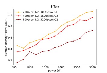
1. B. Elmegaard, F.M. Holm, F. Buhler, Potentials for the electrification of industrial processes in Denmark, The 32nd international Conference on efficiency, cost, optimization, simulation and environmental impact of energy systems, Wroclaw, Poland, October 2019.
2. ROADMAP 2050, A practical guide to a prosperous, low-carbon Europe. Available on-line at https://energy.ec.europa.eu/system/files/2014-10/roadmap2050_ia_20120430_en_0.pdf /3.
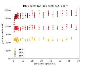
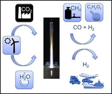
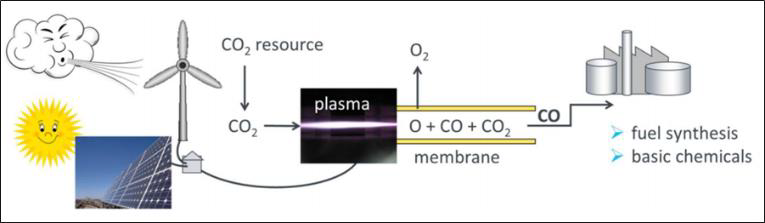
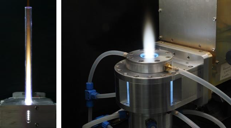
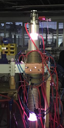
3. M. Radoiu, A. Mello, Scaling up microwave excited plasmas—An alternative technology for industrial decarbonization, Plasma Processes and Polymers, 2024, 21:e2300200, https://doi.org/10.1002/ppap.202300200
4. Fuel Cell and Hydrogen: Hydrogen Roadmap Europe: a Sustainable pathway for the European energy transition, on-line at https://www.fch.europa.eu/publications/hydrogen-roadmap-europe-sustainable-pathway-european-energy-transition (accessed 7th April 2024).
5. D. E. Canfield, A.N. Glazer, P.G. Falkowski, The Evolution and Future of Earth’s Nitrogen Cycle, Science, 2010, 330, pp.192-196.
6. Z. Huang, A. Xiao, D. Liu, X. Lu, K. Ostrikov, Plasma-water-based nitrogen fixation: Status, mechanisms, and opportunities, Plasma Processes and Polymers, 2023, 19, https://doi-org.em-lyon.idm.oclc.org/10.1002/ppap.202100198.
7. R.C. Sanito, M. Bernuy-Zumaeta, H-H. Yang, Y-F. Wang, Volatile Organic Compound (VOC) Reduction from Face Mask Wastes via a Microwave Plasma Reactor, Aerosol and Air Quality Research, 2022, on-line at https://aaqr.org/articles/aaqr-22-07-aac22-0266?fbclid=IwAR0aWvILbhOFystetbktNjawab1LCN5a9yqcHBMewMoMLwJcPYKvuX3JIFw, accessed on 12th April 2024.
8. J. Mizeraczyk, M. Jasiński, Z. Zakrzewski, Hazardous gas treatment using atmospheric pressure microwave discharges, Plasma Physics and Controlled Fusion, 2005, 47, B589, https://doi.org/10.1088/0741-3335/47/12B/S43.
9. M.Radoiu, Studies on atmospheric plasma abatement of PFCs¸ Radiation Physics and Chemistry, 2004, 69, pp. 113-120, https://doi.org/10.1016/S0969-806X(03)00455-9.
10. A.V. Inyushkin, A.N. Taldenkov, V.G. Ralchenko, A.P. Bolshakov, A.V. Koliadin, A.N. Katrusha, Thermal conductivity of high purity synthetic single crystal diamonds, Physical Review B, 2018, 97, 144305.
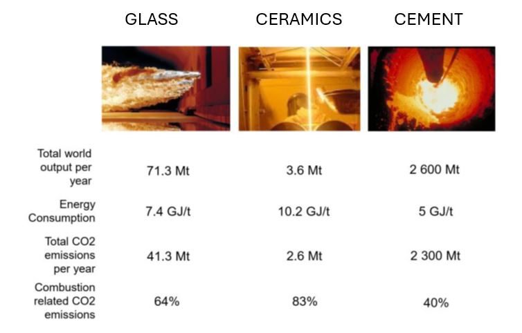
11. A. Schmitz, J. Kamiński, B.M.Scalet, A. Soria, Energy consumption and CO2 emissions of the European glass industry, Energy Policy, 2011, 39, pp.142-155, https://doi.org/10.1016/j.enpol.2010.09.022.
12. E. Benhelal, G. Zahedi, E. Shamsaei, A. Bahadori, Global strategies and potentials to curb CO2 emissions in cement industry, Journal of Cleaner Production, 2013, 51, pp. 142-161,
https://doi.org/10.1016/j.jclepro.2012.10.049.
13. T. Ibn-Mohammed, C.A. Randall, K.B. Mustapha, J. Guo, J. Walker, S. Berbano, S.C.L. Koh, D. Wang, D.C. Sinclair, I.M. Reaney, Decarbonising ceramic manufacturing: A techno-economic analysis of energy efficient sintering technologies in the functional materials sector, Journal of the European Ceramic Society, 2019, 39, pp. 5213-5235, https://doi.org/10.1016/j.jeurceramsoc.2019.08.011.
14. J. Olah, N. Aburumman, J. Popp, M.A. Khan, H. Haddad, N. Kitukutha, Impact of industry 4.0 on environmental sustainability, Sustainability, 2020, 12, p. 4674.
In periods with high output, electrical energy extraction from renewable energy sources (e.g. photovoltaics, wind and water) can easily exceed the load and gets wasted. For maintaining stability of the public mains supply, surplus energy from renewable sources has to be stored, which poses a big challenge. Power-to-X is a general term summarizing technologies for conversion of this kind of surplus energy from renewable sources into matter that either can be stored and reconverted when required, or that will serve as basic materials for the production of e.g. more complex substances in chemical industry or synthetic fuels replacing fossil fuels in the transport sector. Figure 1 shows some examples of Power-to-X applications based on microwave plasma technology.
Examples of Power-to-X applications based on microwave heating and microwave plasma technology are presented in the following chapters.
Microwave-driven depolymerization processes (pyrolysis) are ready to be used for Power-to-Liquid applications, e.g. production of bio-fuel. Standard applications can be found in biomass-to-liquid or waste-to-liquid plants.
Microwave-assisted pyrolysis processes are well suited to recycle a large variety of carbonaceous waste fractions such as tires, sewage sludge, agricultural waste, waste wood, electronic scrap, cables, plastic waste etc. to liquid fuels like heavy
oil, diesel, gasoline and jet fuel. The processes often rely on rapid heating of waste in an oxygen-free environment. The feedstock is introduced into the pyrolysis reactor of Figure 2 through air locks purged with inert gas to prevent oxygen to enter the reactor. Then it is heated by means of microwaves to a temperature level just beyond the threshold for separation of solid and volatile compounds of the feedstock. In a subsequent condensation process, part of the volatile compounds can be transformed into fluids for additional separation. At the end of the pyrolysis process, bio fuels, oils and monomers are extracted via condensers and separated from the remaining char.
Microwave heating is very homogeneous due to the high penetration depth of microwaves into the feedstock, providing a low temperature gradient from the surface to the core of the feedstock.
Storage of surplus electrical energy from renewable sources is a crucial factor for maintaining stability of the public mains supply. Carbon dioxide (CO2) conversion is a promising approach for storing surplus renewable energy. The concept of CO2 conversion is based on splitting CO2 into oxygen (O) and carbon monoxide (CO) radicals in an atmospheric pressure microwave plasma process, see Figure 3. Carbon monoxide (CO) is an industrial gas, which has numerous applications in chemical manufacturing. It can be converted into base chemicals and chemical energy stores such as methanol or methane in existing infrastructures using conventional chemical processes.
CO2 conversion can be efficiently performed with a high-power microwave plasma torch using excess electrical energy from regenerative sources. By separation of the oxygen from the gas mixture, for example via a perovskite membrane – as shown in Figure 4 –, the remaining CO gas can be utilized for the conversion into syngas or higher hydrocarbons. Hence, a zero emission carbon cycle can be established.
The process can be applied wherever CO2 is produced in enriched form: in combustion processes in power plants, in the cement and glass industries, and in breweries where CO2 is a by-product of alcoholic fermentation.
The new generation of MUEGGE’s microwave powerheads, generators and tuning elements enable compact plasma sources at atmospheric pressure for surface and volume treatment. The Atmospheric Plasma Source (APS) from MUEGGE operated at the microwave frequencies of 2.45 GHz and of 915 MHz, respectively, is a feasible tool for production of syngas via CH4 and CO2 conversion. Figure 5 shows microwave plasma torches operated with 6 kW (left) and 3 kW (right) of microwave power, respectively. Microwaves with a frequency of 2.45 GHz are fed into the plasma source resulting in a high field concentration in the middle of the cavity. In this region, the plasma is ignited and sustained. Several kilowatts of microwave power can be injected into the plasma, resulting in gas temperatures of up to 3500 K determined by optical emission spectroscopy.
MUEGGE’s microwave plasma torches are igniting at atmospheric pressure and generate a contact-free plasma while ensuring stable operation in a wide parameter range concerning type of gas, working gas flow and microwave power. Whatever microwave frequency is selected, 2.45 GHz or 915 MHz, microwave plasma torches from MUEGGE are well suited for both synthesis of special gases and supporting chemical reactions with highly reactive gas species, which is key for many Power-to-X applications, e.g. Power-to-Chemicals and Power-to-Gas.
A high-power downstream-plasma-source operated at the microwave frequency of 915 MHz at a few mbar is presented in Figure 6. This device is characterized by its high microwave power input of up to 75 kW, enabling the treatment of high gas flows.
Efficient CO2 dissociation combined with high conversion rates of CH4 – being a prominent example of Power-to-Gas applications – can easily be performed by such highly energetic microwave plasma sources. The H2/CO mole ratio of the syngas is relatively easy to control by adjusting the ratio of CO2/CH4 in the feeding process. Furthermore, the syngas produced by this sources is not only usable for the production of e.g. acetic acid or methyl formate, but also satisfies the H2/CO mole ratio required for the production of various substances when combined with wet syngas processes. The process efficiency can be significantly enhanced by additional application of a suitable catalyst.
The same microwave plasma source-equipment can be used to create a plasma environment to decompose alcohols. When introduced into a water vapor plasma discharge, methanol and ethanol, respectively, decompose to hydrogen. In fact, nearly 100% decomposition of methanol can be achieved in an atmospheric microwave plasma process. The steam reforming reaction
is the most likely source of H2 production in this case, which is confirmed by the fact that no formation of solid carbon was observed. This kind of atmospheric plasma process by application of a microwave plasma torch is very efficient for H2 production from methanol and ethanol, respectively.
A carbon-free, circular economy is required to decrease greenhouse gas emissions. Hydrogen economy is a commonly proposed alternative to the carbon-based economy. However, storing and transporting hydrogen is difficult. Ammonia (NH3) as a carbon-free hydrogen carrier is a relatively safe alternative to hydrogen. Especially in the long term, it is more economic to store ammonia than hydrogen. High-energy electrons and ions as well as highly reactive radicals in an atmospheric microwave torch plasma significantly enhance chemical kinetics. However, the high level of activation energy necessary for the dissociation of the nitrogen molecule is rate limiting in ammonia production. Plasma catalysis uses the synergy effects of plasmas and catalysts for the synthesis of various compounds. In case of ammonia synthesis, plasma catalysis helps to overcome the rate-limiting step of nitrogen dissociation prior to NHX formation. In this perspective, the combination of plasma and catalyst for using their synergies shows high benefits in ammonia production from renewable energy sources.
In general, Power-to-X combines all available options for the effective and flexible use of surplus energy from renewable sources. Power-to-X technologies based on microwave heating and microwave plasma processes are innovative solutions for conversion of electrical energy from renewable sources into material resources such as hydrogen, carbon monoxide, and synthetic gases for storage and recycling – e.g. conversion of electrical energy into gaseous or liquid fuels or chemicals for long-haul trucking, shipping and aviation. Therefore, Power-to-X contributes to the objective of decarbonising the energy systems, and at the same time helps to reduce the proportion of fossil fuels in the key leading markets of transport, travel and chemicals, thus generating ecological, economical and social benefits.
received his Chemistry diploma and PhD degree from the Ludwig-Maximilians-University, Munich, Germany. He has > 20 years of semiconductor experience, working on various positions in etch&strip, CVD and RTP. He joined the MUEGGE group in October 2016 and he currently heads Gerling Applied Engineering, the US branch of MUEGGE GmbH.
MUEGGE provides solutions for breaking down the greenhouse gases CO2 and methane by atmospheric plasma.
Watch our explainer video and learn how our microwave assisted plasma technology can help combat climate change.
The unique properties of the Atmospheric Plasma Source (APS) can be used for applications formerly not available for plasma technology, like Power-to-X and related renewable energy technologies. Power-to-X using APS allows efficient ways to store surplus energy in form of hydrogen, ammonia or fuel.
The thermo-catalytic reforming process (TCR® process) developed through a collaboration between MUEGGE and the Fraunhofer Institute for Environmental, Safety and Energy Technology (Fraunhofer UMSICHT) produces synthetic natural gas, pyrolytic carbon, and synthetic crude oil. Process water is used in the TCR® process; after the process, the water is contaminated with organic compounds like acetonitrile, acetic acid, phenol, pyridine, and pyrroles. For the process water to be recycled, these organic compounds must be removed. MUEGGE’s atmospheric pressure microwave plasma torch [1] was applied for the decontamination of process water.
The decontamination of the process water was performed by Fraunhofer UMSICHT using MUEGGE’s atmospheric pressure microwave plasma torch operated with air at 2.45 GHz, see Figure 1. The treatment process consists of swirling compressed air into the contaminated process water and to inject the resulted air-water flow via a venturi nozzle into the MUEGGE 2.45 GHz plasma torch as to form tiny droplets of water [2]. The smaller the droplets of process water in the pressurized airstream, the higher the probability for complete dissociation of the organic compounds in the high-energy microwave plasma. The desirable result of this atmospheric pressure plasma cleaning process would be the complete conversion of the organic compounds into water vapor and carbon dioxide after dissociation and reaction with hydroxide- and oxygen-radicals formed within the microwave plasma.
At the exit of the 2.45 GHz air plasma, the decontaminated process water can be easily recaptured by rapid cooling, as shown in Figure 2.
To demonstrate the efficiency of the atmospheric pressure microwave plasma decontamination of process water, solutions of 8.74 g ethanol and 16.81 g acetic acid dissolved in 1 l of distilled water were used as substitutes of the organic compounds in the laboratory scale experiments performed by Fraunhofer UMSICHT.
A solution of 8.74 g of ethanol in 1 l of distilled water was injected in compressed air and fed into the atmospheric pressure microwave plasma with a flowrate of 130 l/min, which corresponds to a flowrate of approximately 65 ml/min of the test solution. According to the results obtained by Fraunhofer UMSICHT, the proportion of ethanol dissolved in distilled water was reduced by 92% after its treatment in the air microwave plasma using 2 kW of microwave power.
A test solution of 16.81 g of acetic acid in 1 l of distilled water was added into compressed air and fed into the atmospheric pressure microwave plasma with a flowrate of 130 l/min, which corresponds to a flowrate of approximately 65 ml/min of the test solution. Measurements of the content of acetic acid dissolved in distilled water showed a reduction by 88% after its treatment in the air microwave plasma operated at 2 kW of microwave power.
The laboratory experimental results have shown 92% reduction of ethanol and 88% reduction of acetic acid using the atmospheric pressure air plasma at 2 kW microwave power.
These preliminary results are very promising for high efficiency cleaning of process water from TCR® applications. Working at elevated microwave power levels (e.g., MUEGGE’s 75 kW APS @ 915 MHz) will allow the removal of significantly higher quantities of organic contaminants and the process of considerably higher flows of contaminated process water.
References
[1] Müller, Robert and Gorath, Moritz, et al.: Atmospheric Pressure Plasma Source and Downstream Source: Characteristics and Industrial Applications, Invited Talk, Contributions to 56th Annual Microwave Power Symposium (IMPI 56), Savannah, Georgia (USA), June 14-16, 2022.
[2] Kaiser, Nadine: Behandlung von schwach kontaminierten Abwässern mittels Plasma-Technologie (Treatment of low-contaminated residual water using plasma technology), Bachelor’s Thesis, Technische Hochschule Nuremberg „Georg Simon Ohm“, August 4, 2021.
Fuel cells based on ionomer membranes are very important in applications such as zero emissions vehicles. The major disadvantage of commercially available membranes, e.g., Nafion, in direct methanol fuel cells (DMFC) is their relatively large permeability for methanol, which leads to a drastic degradation of the efficiency of the fuel cell. Figure 8 shows the schematic of a DMFC. Plasma surface treatment of such membranes can reduce their permeability to methanol. In addition, the bond strength of the membrane to the catalyst can be significantly improved by plasma surface treatment.
Figure 1: Schematic of a direct methanol fuel cell (DMFC) [8-9]. |
The porous gas diffusion layer (GDL) is another important component of a fuel cell. It provides a homogeneous gas flow to the catalyst and controls the water content of the cell. In particular, the water management over a wide range of the voltage/current polarization curves is very important for the efficiency of the fuel cell. However, GDLs mostly consist of a strongly hydrophobic material which is critical for a proper water management. A partially hydrophilic GDL is a better choice because it can retain a certain amount of water in the fuel cell.
Figure 2: Completely hydrophobic surface of a gas diffusion layer (GDL) showing hydrophilic properties of the areas exposed to the microwave plasma (cf. water droplets adhered to these hydrophilic areas after low-pressure microwave plasma treatment) [9-10].
Partially hydrophilic properties of the GDL can be achieved by e.g., surface treatment of the GDL in a nitrogen plasma process. When the GDL is covered by a perforated plate, only the uncovered areas of the surface of the GDL will be modified in the plasma process. Consequently, the uncovered areas of the surface of the GDL show hydrophilic properties after plasma treatment (water droplets adhering to these areas – Figure 2), whereas the covered areas of the surface of the GDL retain their initial hydrophilic properties.
The fuel cells with plasma treated GDL show significantly higher cell voltages than the reference fuel cells without plasma treated GDL. This is due to the fact that the membrane of a fuel cell without plasma treated GDL runs dry, especially at higher current densities. When using a plasma treated GDL, a certain amount of water can be retained in the cell leading to a better fuel cell performance.
References
[1] M. Walker, K.-M. Baumgärtner, M. Kaiser, J. Kerres, A. Ullrich, E. Räuchle, J. Appl. Polym. Sci., 1999, 74, 67-73.
[2] M. Walker: Fuel Cells. [online] Homepage: University of Stuttgart, Institute of Interfacial Process Engineering and Plasma Technology (IGVP)
URL: https://www.igvp.uni-stuttgart.de/en/research/plasma-technology/processes/fuel-cells/ [status: June 16, 2021].
Solar power remains an almost inexhaustible reserve of energy on our scale, as well as being geographically accessible, despite its intermittence. However, photovoltaic production has always had its limits. There is still room for improvement when it comes to reflection qualities of the surface coating and more economical ways of producing solar panels. Additionally, our age of fast-paced innovation demands for photovoltaic design for applications never imagined before. Due to its unique performance in surface treatment, Duo-Plasmaline is the revolutionary technology if you want your innovation to work more efficiently than ever. The three main reasons why are:
The effectiveness of light conversion into energy of silicon solar cells is linked to the minimization of reflection losses and surface recombination. Thin plasma-polymerized SiN films are used to improve both properties i.e., the reflection behavior by adjusting the refractive index of the anti-reflection coating and the surface properties to avoid recombination at the surface.
Muegge’s Duo-Plasmaline technology acts superior in creating a homogeneous plasma. Combined with a Plasma Array, it is suitable for continuous and batch processes. Both Duo-Plasmaline and Plasma Array provide highly efficient surface treatment of even thermally sensitive materials due to high radical densities at lowest ion energy of the non-equilibrium microwave plasma at low-pressure.
These properties are critical for SiN films used in photovoltaics: hardness and chemical resistivity are crucial properties of these layers. For this reason, SiN can be applied both as an insulator and as barrier-material for many industrial applications.
Photovoltaic devices will be more profitable if their price can be significantly reduced, e.g., by large-scale production. Thin film solar cells are of particular interest in large-scale production. Glass plates are state-of-the-art substrates for thin film solar modules made of e.g., copper-indium-gallium di-selenide (CIGS). They can be replaced by thin metal foils to reduce both weight and material costs. The heavy glass substrate and the glass covering can be substituted by a systems of thin polymer films deposited in a low-pressure microwave plasma process on the metal plate and on the optical layers on top of the CIGS solar modules.
Standard CIGS solar modules consist of monolithically connected solar cells. Therefore, the metal foil has to be insulated. In addition, diffusion of material impurities and contamination from the metal foil into the CIGS must be prevented by a diffusion barrier. The advantage of using thin metal foils as substrate material is the flexibility of the modules which makes them suitable for mobile applications and wearables.
Plasma processes for deposition of thin polymer films acting as diffusion barriers enable new technologies for economical production of flexible photovoltaic modules. Furthermore, plasma processes can be used for deposition of thin film amorphous silicon (a-Si) solar cells and for microcrystalline silicon (µc-Si) solar cells, thus introducing important new markets for plasma technology.
References
[1] H. Schlemm, A. Mai, S. Roth, D. Roth, K.-M. Baumgärtner, H. Mügge, Surf. Coat. Technol., 2003, 174-175, 208-211.
[2] M. Troia, M. Walker: Diffusion Barrier Layers. [online] Homepage: University of Stuttgart, Institute of Interfacial Process Engineering and Plasma Technology (IGVP)
URL: https://www.igvp.uni-stuttgart.de/en/research/plasma-technology/processes/diffusion-barrier-layers/ [status: June 16, 2021].
In 2007 researchers at Stanford University discovered a solution to the challenges associated with the use of silicon in batteries. They were able to store lithium in tiny silicon nanowires by using new nanotechnology techniques and methods. The dimensions of these silicon nanowires are about one thousand times thinner than the thickness of a sheet of paper. The silicon nanowires swell when they absorb positively charged lithium ions, while their physical properties i.e., size and shape, inhibit the silicon from fracturing and breaking apart.
For the reasons mentioned above, silicon is widely considered to be the future material of choice in anode technology. Battery-builders and automakers want to take advantage of its high theoretical charge capacity. It has been proven that batteries with silicon anodes achieve significantly higher energy per unit volume and per unit weight than today’s commercially available batteries based on carbon-anode designs.
Manufacturing facilities relying on Duo-Plasmaline technology for plasma enhanced chemical vapor deposition (PECVD) of three-dimensional porous silicon layers have high potential for producing silicon nanowire anodes. Figure 5 shows silicon columns three-dimensionally grown by low-pressure microwave plasma deposition for pure silicon anodes.
The combination of Duo-Plasmaline and Plasma Array provides highly efficient surface treatment of even thermally sensitive materials due to high radical densities at low ion energy of the non-equilibrium microwave plasma at low-pressure. The plasma is formed by microwave excitation only, i.e. without the effect of an additional magnetic field. This allows to easily upscale applications for large batches that need a highly precise and homogeneous surface treatment and for materials that require very sensitive processing.
Interested? Would you like to discover how this technology works in detail? Read our in-depth article about Duo-Plasmaline technology. (Link to Article 1)
Should you like know more about how Duo-Plasmaline may benefit your product portfolio and how MUEGGE can customize this technology for you, do not hesitate to contact us.
References:
[3] Applying Solar Technology for Pure Silicon Anodes: Porous Silicon Anodes. [online] Homepage: LeydenJar Energising Technologies, URL: https://leyden-jar.com/technology/ [status: June 16, 2021].
Everybody wants to live on a healthier planet! Innovators from all industries are working hard towards a more sustainable future. Yet in many cases, there is still room for improvement with regards to the efficiency, quality and upscalability of green technologies, especially of those linked to the manufacturing of zero emission car batteries and flexible photovoltaic panels.
MUEGGE’s microwave-powered Duo-Plasmaline systems allow innovators to step up their game when it comes to surface processing and modification in the field of sustainable energy production and storage.
If you want to understand the hows and whys of this technology, this expert review will help you to discover how Duo-Plasmaline systems enable high radical densities, high plasma homogeneity on large treated areas, and easy upscaling.
Microwave plasma excitation at low-pressure is based on the acceleration of free electrons within the electric field of the microwaves. Ideally, once formed via gas ionization, the electrons collide with each other and with neutral and charged species producing an avalanche effect which leads to the formation of the plasma. The operating pressure of the vacuum chamber is an important parameter in this process: at low-pressure the mean free path of the accelerated free electrons is significantly shorter than the dimensions of the vacuum chamber and a non-equilibrium plasma is formed, characterized by neutrals and ions at ambient temperature and by “hot” accelerated free electrons. When the pressure in the vacuum chamber is further reduced so that the mean free path of the free electrons is in the range of the dimensions of the vacuum chamber, the probability of collision between the free electrons with the walls of the vacuum chamber increases significantly, thus inhibiting the avalanche effect which is essential for forming and sustaining the plasma.
On the other hand, increasing the pressure will allow the energy transfer to heavy particles like neutrals and ions, causing the plasma to gradually thermalize. Therefore, the bulk temperature of the plasma increases. On the other hand, if keeping the microwave energy constant by increasing the particle density, e.g., by increasing gas flow, the excitation energy will not be sufficient to maintain the plasma.
Increasing the electron density at constant pressure inhibits microwave propagation. At the so-called critical density, microwaves can no longer penetrate the plasma and are reflected, the plasma acting like a conducting wall.
N.B. The critical density is proportional to the square of the frequency of the electromagnetic wave.
Based on the principles underlined above, many microwave plasma sources have been conceived as to take advantage of the elevated efficiency of the high radical density that is typical to microwave plasmas. However, the formation of specific modes, of standing waves and the fact that the vacuum wavelength of the microwaves can have the same geometrical dimension as the material to be treated can lead to inhomogeneous plasma treatment of the substrate’s surface. Scaling-up microwave plasma sources for large substrates is an important challenge. The Duo-Plasmaline microwave plasma source as well as the Plasma Array (based on multiple Duo-Plasmaline) perfectly measure up to these challenges.
The Duo-Plasmaline is a low-pressure microwave plasma source. The plasma is formed by microwave excitation only i.e., without the effect of an additional magnetic field. To put it simply, the Duo-Plasmaline is an inverse fluorescent tube excited by microwaves: a coaxial line is mounted through the vacuum vessel i.e., the microwave energy transmission line (antenna) made of electrically conducting material and powered by microwaves from both sides. Inside the vacuum vessel, the outer coaxial conductor is replaced by a dielectric tube made of glass, quartz or ceramics. The inside of the dielectric tube is at atmospheric pressure, whereas the outside i.e., the vacuum vessel, is at low pressure, preferably in the range between 10 Pa and 1000 Pa. Microwaves can pass the dielectric tube and propagate into the low-pressure regime of the vacuum vessel. When the electric field strength of the microwaves exceeds the breakdown field strength, a discharge ignites in the low-pressure regime at both ends of the Duo-Plasmaline where the outer coaxial conductor is replaced by the dielectric tube. The short plasma ‘hoses’ formed at both ends of the Duo-Plasmaline are electrically conducting media and thus replace the missing outer coaxial conductor. With the increase of the microwave power, the plasma extends from both ends along the dielectric tube, until an axially homogeneous plasma is formed – see Figure 1.
The formation of an axially homogeneous low-pressure plasma around a Duo-Plasmaline with a length of over 3 m has been demonstrated for applications using only a few kW of 2.45 GHz microwave power.
A two-dimensional Plasma Array source is obtained when arranging equidistantly two or more parallel Duo-Plasmalines. While a Duo-Plasmaline provides an axially homogeneous plasma, the Plasma Array generates a large and homogeneous plasma, see Figure 2. Consequently, a Duo-Plasmaline is preferably used for plasma surface treatment in continuous in-line processes, whereas a Plasma Array is suitable for continuous and batch processes. Both the Duo-Plasmaline and the Plasma Array allow highly efficient surface treatment even for thermally sensitive materials because of the high radical density at low ion energy of the non-equilibrium microwave plasma at low-pressure.
Due to its modular design, the Plasma Array is easy to adapt to the dimensions of the substrate by configuring the number and the length of the Duo-Plasmalines in the Plasma Array. Hence, the active plasma area can be scaled in width and length.
A schematic of a Plasma Array consisting of four Duo-Plasmalines in a process chamber for plasma surface treatment at low-pressure is shown in Figure 3. The four Duo-Plasmalines are supplied with microwave energy from the left and from the right. The microwave energy is generated by two magnetron-heads on each side. Each magnetron-head supplies two Duo-Plasmalines with microwave energy via a power splitter. Power split equally to two or more Duo-Plasmalines guarantees the best plasma homogeneity on the substrate.
Figure 4 shows a Plasma Array consisting of six Duo-Plasmalines with a length of 160 cm each, thus forming an active plasma area of approximately 150 cm x 200 cm for e.g., coating of solar cells with silicon-nitride.
Apart from deposition of thin films, Muegge’s Duo-Plasmalines and Plasma Arrays sources are also used for plasma assisted surface treatment like surface activation, etching, cleaning and even sterilization. Today and going forward, this exciting technology offers a broad range of revolutionary processes for sustainable energy production and storage. Examples of exciting applications for non-equilibrium microwave plasma processes at low-pressure include the deposition of silicon nanowires for novel lithium-ion batteries and surface modifications in fuel cell technology.
Visit our website to discover our hands-on cases and examples of Duo-Plasmaline and Plasma Arrary and to find out how you can use them to support your innovations and product development.
References
[1] A. Schulz, P. Büchele, E. Ramisch, O. Janzen, F. Jimenez, C. Kamm, J. Kopecki, M. Leins, S. Merli, H. Petto, F. R. Mendez, J. Schneider, U. Schumacher, M. Walker, U. Stroth, Contrib. Plasma Phys., 2012, 52, 607-614.
[2] M. Walker, A. Schulz: Duo-Plasmaline. [online] Homepage: University of Stuttgart, Institute of Interfacial Process Engineering and Plasma Technology (IGVP)
URL: https://www.igvp.uni-stuttgart.de/en/research/plasma-technology/sources/plasmaline/ [status: June 16, 2021].
MUEGGE Group
Hochstrasse 4 – 6
64385 Reichelsheim
Germany
Gerling Applied Engineering, Inc.
P.O. Box 580816
Modesto, CA 95358-0816
USA
Sie benötigen eine besondere Lösung für Ihren individuellen Prozess?
Sie benötigen eine besondere Lösung für Ihren industriellen Prozess?
Sie müssen den Inhalt von reCAPTCHA laden, um das Formular abzuschicken. Bitte beachten Sie, dass dabei Daten mit Drittanbietern ausgetauscht werden.
Mehr InformationenSie sehen gerade einen Platzhalterinhalt von Google Maps. Um auf den eigentlichen Inhalt zuzugreifen, klicken Sie auf die Schaltfläche unten. Bitte beachten Sie, dass dabei Daten an Drittanbieter weitergegeben werden.
Mehr Informationen